

Booth's Multiplier :
Booth's multiplication algorithm is an algorithm which multiplies 2 signed integers in 2's complement. The algorithm is depicted in the following figure with a brief description. This approach uses fewer additions and subtractions than more straightforward algorithms.
| The multiplicand and multiplier are placed in the m and Q registers respectively. A 1 bit register is placed logically to the right of the LSB (least significant bit) Q0 of Q register. This is denoted by Q-1. A and Q-1 are initially set to 0. Control logic checks the two bits Q0 and Q-1. If the twi bits are same (00 or 11) then all of the bits of A, Q, Q-1 are shifted 1 bit to the right. If they are not the same and if the combination is 10 then the multiplicand is subtracted from A and if the combination is 01 then the multiplicand is added with A. In both the cases results are stored in A, and after the addition or subtraction operation, A, Q, Q-1 are right shifted. The shifting is the arithmetic right shift operation where the left most bit namely, An-1 is not only shifted into An-2 but also remains in An-1. This is to preserve the sign of the number in A and Q. The result of the multiplication will appear in the A and Q. |  |
Design Issues :
Booth's algorithm can be implemented in many ways. This experiment is designed using a controller and a datapath. The operations on the data in the datapath is controlled by the control signal received from the controller. The datapath contains registers to hold multiplier, multiplicand, intermediate results, data processing units like ALU, adder/subtractor etc., counter and other combinational units. Following is the schemetic diagram of the Booth's multiplier which multiplies two 4-bit numbers in 2's complement of this experiment. Here the adder/subtractor unit is used as data processing unit.M, Q, A are 4-bit and Q-1 is a 1-bit rigister. M holds the multiplicand, Q holds the multiplier, A holds the results of adder/subtractor unit. The counter is a down counter which counts the number of operations needed for the multiplication. The data flow in the data path is controlled by the five control signals generated from the controller. these signals are load (to load data in registers), add (to initiate addition operation), sub (to initiate subtraction operation), shift (to initiate arithmetis right shift operation), dc (this is to decrement counter). The controller generates the control signals according to the input received from the datapath. Here the inputs are the least significant Q0 bit of Q register, Q-1 bit and count bit from the down counter.

Booth's Multiplier :
Basic stage
Multiple choice questions:
- For a 4 bit number, what is the maximum positive integer which can be expressed in 2's complement?
- For a 4 bit number, what is the minimum negative integer which can be expressed in 2's complement?
- In which notation, 0 has two representations?
- Sign extension is a step in
8
7
16
15
-7
-15
-16
-8
Sign magnitude
1's complement
2's complement
None of these
Arithmetic left shift
Signed 16 bit integer addition
Floating point multiplication
None of these
Subjective questions:
- How to represent a negative integer in 2's complement notation?
- What are the different approaches for multiplication?
- What is the sign extention rule for 2's complement numbers?
- Is there any difference between the 2's complement representation of a numeber and the 2's complement of a number? If yes then explain.
Advanced stage
Multiple choice questions:
- Which of the following gives best performance with Booth's algorithm?
- Booth's algorithm is faster du to less number of addition and subtraction and can handle signed numbers
- Booth's algorithm increases space in case of fixed point signed multiplication
0000 1111
1111 0000
1111 1111
1010 1010
True
False
True
False
2's complement of 7 is?
11100
11001
10111
10100
Subjective questions:
- What is the difference between combionational multiplier and Booth's multiplier?
- Why Booth's multiplier is faster than other approaches like shift and add multiplier?
- How Booth's multiplier handles the signed integer while others cannot?
- Prove that the multiplication of two m-bit numbers in base R gives a product of no more than 2m digits.
Booth's Multiplier :
Procedure to perform the experiment on the given working module which multiplies two 4-bit numbers- Start the simulator as directed.This simulator supports 5-valued logic.
- To perform the experiment on the given modules, we need the datapath specified for booth's multiplication, a controller with a specified state chart, a clock input, bit switch (to give input, which will toggle its value with a double click), bit displays (for seeing output), wires.
- Instantiating the controller: A control unit can be seen as a finite state machine, so its behavior can be represented in a state table. The controller of the simulator accepts the Moore type state chart and must contain an end state. State names will automatically be generated in the form of S
- Number of states: 7
- Number of inputs: 3
- Number of outputs: 5

- Instantiate the Booth's multiplier datapath from the sequential ckt drawer in the palette (by clicking as mentioned previously).
- The pin configuration of the component is shown whenever the mouse is hovered on any canned component of the palette or pressing the show pin configuration button on the toolbar will show it constantly in the left pane. Pin numbering starts from 1 and from the bottom left corner(indicating with the circle) and increases anticlockwise.
- Pin configuration of the datapath module:
- M : Multiplicand (4 bit), Q : Multiplier (4 bit)
- Initialization : Inl:1, preset:1, set M, Q, start clock
- Starting multiplication: Inl:0, preset:0, start clock
- Result: FQ0 to FA3, at end state (here it is S6). These are the content of A(4bit) and Q(4bit) register, total 8 bit (FQ0 is LSB, FA3 is MSB)
- I/P:
- Clk:32, Inl:31, preset:30
- Control pins: load:29, add:28, sub:27, shift:26, dc:25
- Multiplicand: M3 : 24, M2 : 23, M1 : 22, M0 : 21
- Multiplier: Q3 : 20, Q2 : 19, Q1 : 18, Q0 : 17
- O/P: FQ-1 is output of Q-1 bit register, similarly FQ0 to FQ3 are for Q register and FA0 to FA3 are for A register.
- Datapath to controller input: Count, clkToController, FQ-1, FQ0
- Count : 16, clkToController : 15, FQ-1 : 14, FQ0 : 13
- FQ1 : 12, FQ2 : 11, FQ3 : 10
- FA0 : 9, FA1 : 8, FA2 : 7, FA3 : 6
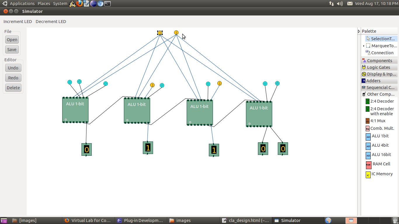
- To connect any two components select the Connection menu of Palette, and then click on the Source terminal and click on the target terminal. According to the following diagram connect all the components. Connect the controller outputs to the specified control input terminals of the datapath, specified datapath outputs to the inputs of the controller, the clock input, Bit switches with the inputs and Bit displays component with the outputs (from Display and Input drawer of the pallet,if it is not seen scroll down in the drawer). After the connection is over click the selection tool in the pallete.

- At first initialize the multiplier by giving the specified inputs specified earlier, this will load the multiplier and multiplicand, then start the multiplication operation by giving the specified inputs specified earlier. At the end state (S6), the multiplication result will be seen through ports FQ0 to FA3 (FQ0 is LSB, FA3 is MSB). The current state of the controller is shown in the left pane as it transits from one state to another. The controller can be reset by clicking the reset controller button in the top toolbar, to start with a new input.
Components :
To build the 4 bit Booth's multiplier, we need :
- Controller
- Rigisters, Adder/subtractor unit, multiplexer, down counter, logic gates to construct the datapath
- Inputs
- Outputs
- Wires to connect
Objective of 4 bit Booth's multiplier:
- Understanding behaviour of Booth's multiplication algorithm from working module and the module designed by the student as part of the experiment
- Designing Booth's multiplier with a controller and a datapath. This will also help in the learning of control unit design as a finite state machine
- Understanding the advantages of Booth's multiplier
- It can handle signed integers in 2's complement notion
- It decreases the number of addition and subtraction
- It requires less hardware than combinational multiplier
- It is faster than straightforward sequential multiplier
Examining behaviour of 4 bit Booth's multiplier for the working module and module designed by the student as part of the experiment (refer to the circuit diagram):
Set M as 0111 which is 7 and Q as 0101 which is 5. Now start the multiplication operation and observe the results including the intermediate results. The Booth's algorithm on those inputs works as the following diagram, so the circuit must behave according to it.

Recommended learning activities for the experiment: Leaning activities are designed in two stages, a basic stage and an advanced stage. Accomplishment of each stage can be self-evaluated through the given set of quiz questions consisting of multiple type and subjective type questions. In the basic stage, it is recommended to perform the experiment firstly, on the given encapsulated working module, secondly, on the module designed by the student, having gone through the theory, objective and procuder. By performing the experiment on the working module, students can only observe the input-output behavior. Where as, performing experiments on the designed module, students can do circuit analysis, error analysis in addition with the input-output behavior. It is recommended to perform the experiments following the given guideline to check behavior and test plans along with their own circuit analysis. Then students are recommended to move on to the advanced stage. The advanced stage includes the accomplishment of the given assignments which will provide deeper understanding of the topic with innovative circuit design experience. At any time, students can mature their knowledge base by further reading the references provided for the experiment.
- if value is UNKNOWN, wire color= maroon
- if value is TRUE, wire color= blue
- if value is FALSE, wire color= black
- if value is HI IMPEDENCE, wire color= green
- if value is INVALID, wire color= orange
Test plan:
- Compute the multiplication of 0101 which is 5 and 1010 which is -6 with the Booth's multiplication
- Test the multiplication of two negative numbers and with two positive numbers
Assignment Statements :
- Design a 4-bit Booth's multiplier circuit with a different controller behaving differently other than specified in this experiment
- Design a 4-bit shift and add multiplier
- Design a 8-bit shift and add multiplier
- Design a 6-bit Booth's multiplier circuit
Booth's Multiplier :
General guideline to use the simulator for performing the experiment:- Start the simulator as directed. For more detail please refer to the manual for using the simulator
- The simulator supports 5-valued logic
- To add the logic components to the editor or canvas (where you build the circuit) select any component and click on the position of the canvas where you want to add the component
- The pin configuration is shown when you select the component and press the 'show pinconfig' button in the top toolbar or whenever the mouse is hovered on any canned component of palette
- To connect any two components select the connection tool of palette, and then click on the source terminal and then click on the the target terminal. By pressing the 'change connection type' in the toolbar the type of the connection can be toggled between shortest path type or manhattan type. Default connection type is mahattan.
- To move any component select the component using the selection tool and drag the component to the desired position
- To give a toggle input to the circuit, use 'Bit Switch' which will toggle its value with a double click
- Use 'Bit Display' component to see any single bit value. 'Digital Display' will show the output in digital format
- undo/redo, delete, zoom in/zoom out, and other functionalities have been given in the top toolbar for ease of circuit building
- Use start/stop clock pulse to start or stop the clock input of the circuit
- Use 'plot graph' button to see input-output wave forms
- Users can save their circuits with .logic extension and reuse them
- After building the circuit press the simulate button in the top toolbar to get the output
- If the circuit contains a clock pulse input, then the 'start clock' button will start the simulation of the whole circuit. Then there is no need to again press the 'simulate' button
- If you are using linux platform then click on 'Linux(32 bit)' or if you are using then click on 'Windows(32 bit)'

The combinational logic between the control signals of the controller and the control pins of the registers are to satisfy different operational conditions of individual components. In this design, the controller controls only the multiplication process, the initialization has been seperated, so a multiplexer is used to the clock port of the controller to deactivate ot during initialization. Except M, A, Q, Q-1 registers one more 4-bit register has been used which works as temporary storage. With the preset, the down counter is set to all one which is then decremented. The controller state chart is designed in such a way that at each state it activates only one control signal. The controller of this circuit behaves according to the state chart shown in the procedure section of this experiment. A and Q will hold the final multiplication result.
Click here to download the older version of simulator
Click here to download the new version of simulator
OR
Launch the older version of Simulator
Launch the new version of Simulator
Once the simulator is downloaded, open the command prompt, then go to the directory where you have saved it using cd command and then give the following command to run the simulator:
java -jar coaSimulator.jar
Click here to download the older version of simulator
Click here to download the new version of simulator
OR
Launch the older version of Simulator
Launch the new version of Simulator
Once the simulator is downloaded, open the command prompt, then go to the directory where you have saved it using cd command and then give the following command to run the simulator:
java -jar Simulator.jar
Booth's Multiplier :
References :
Books:
- Computer Architecture and Organization - John P. Hayes
- Computer Organization and Architecture - William Stallings
- Digital Logic and Computer Design - M. Morris Mano. Pearson Education - Prentice Hall.
- Digital Principles Foundation of Circuit Design and Application - Arun Kumar Singh. New Age Publishers.
- The Art of Electronics - Paul Horowitz and Winfield Hill (1989). Cambridge University Press
- Modern Dictionary of Electronics - Rudolf F. Graf (1999). Newnes
Web Sites:
Virtual Lab is an initiative of Ministry of Human Resource and Development(MHRD) under National Mission of Education through ICT to provide an interactive environment over the internet for creating and conducting different laboratory experiments by sharing the costly equipments and the resources.
For more information about the Virtual Lab,please visit http://www.vlab.co.in/
Developers of Logic Design and Computer Organization Virtual Lab
- Dr. Chittaranjan Mandal Professor, Computer Science & Engineering
- Gargi Roy Senior Project Assistant
- Devleena Ghosh
Professor, Information Technology
IIT Kharagpur
Target Audience:
Under graduate students.
Courses Aligned With:
Computer organization and artitecture.
Pre-requisite Softwares:
- 32 bit java runtime environment and java 1.6 or above
- Recommended browser: mozilla firefox, google chrome
Objectives:
The Objective is to Expose the students to the various key aspects of Computer Organisation by enabling them to perform FPGA based prototyping of experiments with support of a virtual environment. The primary need for virtualisation here is multifold.
- Digital Logic and Computer Organisation are core courses in most of the Undergraduate Curricula of the entire Electrical Sciences Discipline(Computer Science / Engg., Electronics, Electrical) etc.
- Many colleges/institutes cannot procure sufficient number of FPGA boards for their students.
- Even when such FPGA boards are available, making them available round the clock is difficult.
- Expert help is required to effectively use these FPGA boards and such help can be easily channeled through a virtual environment.
- Helps to standardize the set of Experiments to a large extent.
Contact Information:
Mailing Address and Contact Information:Department of Computer Science & Engineering, IIT Kharagpur
Office : +91-3222-2882255
Postal Address:
Indian Institute of Technology Kharagpur, Kharagpur - 721302, INDIA Telephone Number +91-3222-255221 | FAX : +91-3222-255303
Tutorial on UI for lab:
Introduction:
- The simulator contains a pallete on the right hand side. This pallete contains all the components and tools . Tools are used to act up on the components. Different tools:
- Selection tool- used for selecting components
- Marquee tool- used for selecting many components at a time by draggiung the mouse in the design area(editor).
- Connection tool- used for connecting components
- Components have been catagorized according to their functionality and put into different drawers in the pallete. The area under every drawer is scrallable, if you are unable to see all the components in a particular drawer just click on the area and scroll. Different drawers:
- Circuits- contains 8 and 16 terminal circuits and flow container which can hold other circuit components.
- Logic gates- contains all kinds of basic logic gates.
- Display and inputs- contains all kinds of component needed to give input to the circuit and displaying outputs of the circuit.
- Adders- contains different types of adder circuits.
- Sequential ckt- contains basic flipflops for designing sequential circuits.
- Other Components- contains different kinds of components like decoders, multiplexers, arithmetic logic units(ALU), memory elements(RAM cell) required to design combinational circuits.
- To add the components to the editor select any component(first click on the selection tool then click on the desired compoent) then finally click on the position of the editor window where you want to add the component.
- The pin configuration of a component is shown whenever the mouse is hovered on any canned component of the palette. Pin numbering starts from 1 and from the bottom left corner(indicating with the circle) and increases anticlockwise.
- To connect any two components select the Connection tool in the palette, and then click on the Source terminal and click on the target terminal(no drag and drop, simple click will serve the purpose). After the connection is over click the selection tool in the pallete.
- To move any components select the Selection Mode and drag the component after selecting it.
- If needed select any component in the editor while designing your circuit and use Undo, Redo, Delete,Zoom in, Zoom out buttons to get corresponding functionalities. Open and Save options are under development.
- As the automated clock is under development and the simulator is under modification for sequencial circuits, for the time being please use individual clock(Bit switch which toggle its value with a double click) for each flipflop.
- The simulator is currently under modification for sequential circuits, now it is working properly for combinational circuits but may not give proper output for sequential circuits.
Description of Components:
General components:- Digital display: it can be used to give input and as well as to see the output in the decimal format, its right most terminal is the LSB(least significant bit) and the left most terminal is the MSB(most significant bit), in the editor after selecting a particular digital display you can use 'Increment LED' and 'Decrement LED' buttons in the top left corner of the simulator to increment and decrement its value respectively.
- Bit display: it displays a single bit value.
- V+: it gives 1 as input.
- Ground: it gives 0 as input.
- Bit switch: it gives 1/0 input, it toggels its value with a double click.
Specific components:
Pin numbering starts from 1 and from the bottom left corner(indicating with the circle) and increases anticlockwise. Pin configurations of all the components-
- Half adder: i/p: 5,8 o/p: sum=4, carry=1
- Full adder: i/p: 5,6,8 o/p: sum=4, carry=1
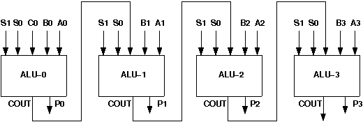
- RCA 4 bit: (4 bit ripple carry adder) i/p: A0=13,A1=14,A2=15,A3=16; B0=17,B1=18,B2=19,B3=20; C0=21 o/p: S0=12,S1=11,S2=10,S3=9,Cout=8
- Wallace tree adder: (adds 3 4-bit numbers) i/p: A0=13,A1=14,A2=15,A3=16; B0=17,B1=18,B2=19,B3=20; C0=21,C1=22,C2=23,C3=24 o/p: S0=12,S1=11,S2=10,S3=9,Cout=8
- RS flipflop: i/p: R=5, S=8, Clk=7 o/p: Q=4, Q'=1
- D flipflop: i/p: D=5, Clk=8 o/p: Q=4, Q'=1
- T flipflop: i/p: T=8, Clk=7 o/p: Q=4, Q'=1
- JK flipflop: i/p: J=5, K=8, Clk=7 o/p: Q=4, Q'=1
- 2:4 Decoder: i/p: A0=5,A1=7 o/p: D0=4,D1=3,D2=2,d3=1
- 2:4 Decoder with enable: i/p: A=6,B=5, Enable=8 o/p: D0=4,D1=3,D2=2,d3=1
- 4:1 Mux: i/p: I0=9,I1=10,I2=11,I3=12,S0=13,S1=14 o/p: F=8
- Combinational Multiplier: i/p: multiplicand: A0=13,A1=14,A2=15,A3=16 Multiplier: B0=9,B1=10,B2=11,B3=12 o/p: S0=8,S1=7,S2=6,S3=5,S4=4,S5=3,S6=2,S7=1
- ALU 1 bit: i/p: A0=9, B0=10, C0=21 S0=12,S1=13 o/p: F=8, Cout=7
- 4 bit ALU: i/p: A0=13,A1=14,A2=15,A3=16; B0=17,B1=18,B2=19,B3=20; C0=21;S0=22,S1=23 o/p: F0=12,F1=11,F2=10,F3=9,Cout=8
- 16 bit ALU: i/p: A1=13,A2=15; B1=14,B2=16; Cin=9,S0=12,S1=11,S2=10 o/p: Cout=6,F2=7,F1=8
- RAM Cell: i/p=5, select=8, R/W'=6, o/p=4, R/W'=1 for read operation, R/W'=0 for write operation
- IC Memory: R/W'=16 Memory Enable=15, Address i/p=14,13 Data i/p=12,11,10 Data o/p=6,7,8 R/W'=1 for read operation, R/W'=0 for write operation
- Direct Mapped Cache:
- pin-32= S(selects whether user wants to perform cache write or cache mapping)
- pin-31= R/W'A(selects whether user wants to input the address or cache mapping)
- pin-30=A3, pin-29=A2, pin-28=A1, pin-27=A0 (thise 4 pins are used to give address input). A3 is the most significant bit and A0 is the least significant bit. A3 and A2 will be compared with the tag. A1 and A0 will select the corrsponding set.
- pin-26= R/W'D(selects whether user wants to input in the set of cache or cache mapping)
- pin-25= M1, pin-24=M0 (M1 is the most significant bit and M0 is the least significant bit). thiese two bits are used for cache writhe purpose, it selects the particular set of which user wants to give inputs to the valid bit, tag bits and data bits.
- pin-23= Den(this is an enable input which has to set for any write purpose in the cache).
- pin-21= valid bit
- pin-20= T1, pin-19=T0 (T1 is the most significant bit and T0 is the least significant bit). These are tag bits.
- pin-18= D1, pin-17=D0 (D1 is the most significant bit and D0 is the least significant bit). These are data bits.
- pin-14= Hit/Miss bit(if it gives 1 then hit otherwise miss)
- pin-15= F1, pin-16=F0 (F1 is the most significant bit and F0 is the least significant bit). These are output data bits and will be given only when there is a hit.
- Essential pin configurations for writing in cache: S=1, R/W'A=0, R/W'D=0, Den= 1
- Essential pin configurations for cache mapping: S=0, R/W'A=1, R/W'D=1, Den= 0
Testing process:
- To test your circuit give some input(through Digital display or Bit switch or V+ or Ground), if you use the Digital display or Bit switch you can then give different input to you circuit through incrementing/decrementing the Digital display or double clicking the Bit switch, the other two gives constant inputs.
- to see the output, connect Digital display or Bit display to the output terminals of your circuit.
Go to the Top
Frequently Asked Questions:
What is virtual lab?
The Virtual Laboratory is an interactive environment for creating and conducting simulated experiments: a playground for experimentation. It consists of domain dependent simulation programs, experimental units called objects that encompass data files, tools that operate on these objects.
What are the advantages of virtual lab?
Virtual Logic Design and Computer Organisation lab enables students to perform FPGA based prototyping of experiments with support of a virtual environment. The primary need for virtualisation here is multifold.
- Digital Logic and Computer Organisation are core courses in most of the Undergraduate Curricula of the entire Electrical Sciences Discipline ( Computer Science / Engg., Electronics, Electrical ] etc.
- Many colleges/institutes cannot procure sufficient number of FPGA boards for their students.
- Even when such FPGA boards are available, making them available round the clock is difficult.
- Expert help is required to effectively use these FPGA boards and such help can be easily channeled through a virtual environment.
- Helps to standardize the set of Experiments to a large extent.
What is eclipse platform?
Eclipse is a Java-based, extensible open source development platform. By itself, it is simply a framework and a set of services for building a development environment from plug-in components. Eclipse comes with a standard set of plug-ins, including the Java Development Tools (JDT).
Which framework is used to develop the application?
We have used the eclipse gef framework. The Graphical Editing Framework (GEF) allows developers to take an existing application model and quickly create a rich graphical editor.
What is platform independent application?
Applications that run under particular operating systems and/or particular hardwares are called platform dependent application whereas platform independent applications can run in any operating environment.
What are the experiments which can be performed by the Virtual Logic Design and Computer Organization lab?
The experiments that will be supported by this lab are given below:
- Design of a ripple carry adder
- Design of a carry-look-ahead adder
- Design of registers and counters
- Design of a wallace tree adder
- Design of combinational multipliers
- Design of a Booth’s multiplier
- Design of an ALU
- Design of memory units
- Design of direct mapped cache
- Design of associative cache
- Design of combinational dividers
- CPU design