Why ASM
- A digital system often has a data path which is controlled by a finite
state m/c serving as the controller
- A state m/c representation may be rather cumbersome when there are a large number
of inputs and outputs
- Compared to a state diagram, it's a flowchart based representation of the sequence
of operations to be carried
- Offers the advantage of not requiring the listing of all input conditions and possible
output conditions
- Example of some digital systems where the controller may be represented via ASM:
multiplier for unsigned integers, Booth's multiplier,
floating point adder

ASM chart
- It depicts links between the various operations that need to be carried out
- Three types of symbols used in ASM charts are as follows:
- a rectangle is used to represent outputs not dependent on input conditions,
such as the flip-flop outputs
- a diamond or hexagon is associated with conditional execution of operations;
for n inputs, 2n branches are possible
- a rectangle with rounded corners is used to yield the conditional outputs
(dependent on inputs)

- Circuits associated with the ASM symbols are depicted next
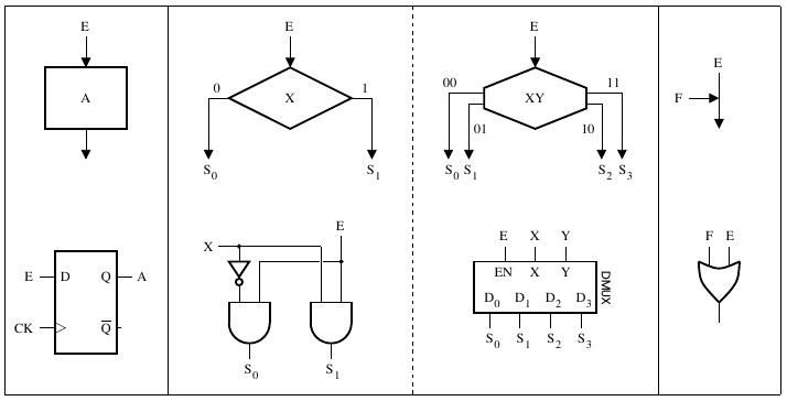
- Section of an ASM chart and corresponding logic circuits are shown

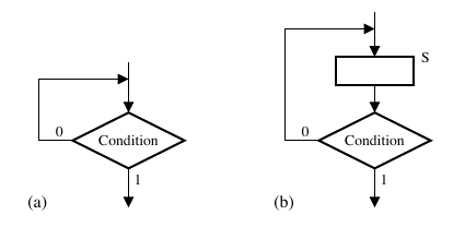
- Caution needs to be exercised to avoid races;
figure (a), below, admits races and should be avoided
- An ASM chart and its associated Moore m/c is shown next
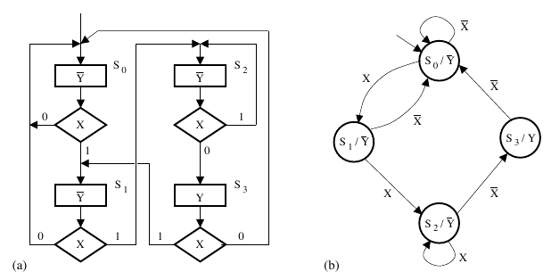
- In this ASM chart, note that all joins are from mutually exclusive branches
of computation
- The ASM chart fragment shown next admits concurrency
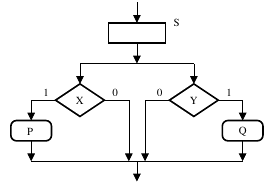
- The tests on X and Y can be done concurrently
- However, the concurrent branches need to join subsequently, as indicated
- Joining using an OR gate will not be adequate, instead an AND gate may be
used to synchronise the concurrent brances, if the inputs remain steady
- If not, a Muller-C element (not covered) should be used
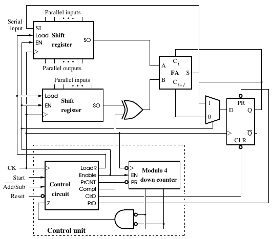
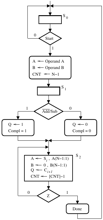
Serial adder example
Serial adder data path
Serial adder ASM chart
Exercises
- Formulate the datapath for a transmitter for an Hamming SECC for four data bits
(and three parity bits) and the ASM chart for the associated controller
- Formulate the datapath for a receiver for an Hamming SECC for four data bits
(and three parity bits) and the ASM chart for the associated controller
- Note that there is scope for parallelism for both parity bit generation and
error correction; that should be accommodated in the design of your ASM charts
(Muller-C element will not be needed)


