This is a report made by Surya Addanki and Satish Kumar Reddy Karri for our Computer Graphics term project.
Table of Contents:
Objective
Projection and animation of arbitrary number of objects given in obj format using a computer graphics technique called "Ray casting" to make them look realistic.
Specifications
Input: Set of objects(in obj format), respective centers, scaling factors, colors, position of light and camera
Output: The scene as seen from the camera in a \(500\times500\) PPM image
Other details
- The objects are assumed to be in a \(500\times500\times500\) room centered at \((250,250,-250)\). So, the centers of the objects and their scaling factors must be chosen accordingly so that the objects don't go outside the room.
- The specifications like room size, output image dimensions can be changed by changing the macro WALL_SIDE in the tracer.h file.
- To turn off the effect of shadow of one object on another, the variable CrossShadows can be set to false.
Introduction
In computer graphics, ray tracing is a rendering technique for generating an image by tracing the path of light as pixels in an image plane and simulating the effects of its encounters with virtual objects. The technique is capable of producing a very high degree of visual realism, usually higher than that of typical scanline rendering methods, but at a greater computational cost. This makes ray tracing best suited for applications where the image can be rendered slowly ahead of time, such as in still images and film and television visual effects, and more poorly suited for real-time applications like video games where speed is critical.
The first ray tracing algorithm used for rendering was "ray casting". The idea behind ray casting is to shoot rays from the eye—one per pixel—and find the closest object blocking the path of that ray. Using the material properties and the effect of the lights in the scene, this algorithm can determine the shading of this object. The simplifying assumption is made that if a surface faces a light, the light will reach that surface and not be blocked or in shadow.We used ray casting to project arbitrary objects given as triangular meshes in obj format.
Overview of ray casting
The ray casting algorithm takes an image made of pixels. We shoot a primary ray from the eye through every pixel of the image into the scene. The direction of that primary ray is obtained by tracing a line from the eye to each pixel in the image. Now we check if this ray intersects any of the objects in the scene. If the ray intersects more than one object, we pick the object with minimum z value and use the properties of the intersection point to assign the pixel colour.
Procedure of ray casting
In our case, every object is given as set of trianglular meshes. Hence, to check the intersection of primary ray with the object, we need to check the intersection with all the trianguled faces of the object. We initially find the intersection of the ray with the plane containing the triangle, then we check if the point of intersection lies within the face using barycentric coordinates technique.
If the point indeed lies on the object, then we shoot another ray from the point to the light source. If this ray intersects any of other objects in the scene, it means that light is obstructed from reaching that point. So, it becomes a shadow(only ambient light is present). Otherwise, we use the illumination model to find the intensity of light at that point.
Illumination model
Illumination model is how light reflects from surfaces and produces what we perceive as color. It is used to calculate the intensity of light that we should see at a given point on the surface of an object. The illumination model we used is Phong Illumination Model.
The three important components of this model are :
- Ambient Light
- Diffuse Reflection
- Specular Reflection
Ambient Light :
A diffuse and omnipresent light, which is usually faint and impinges equally on all surfaces from all directions, is ambient light. The resulting intensity at each point of the object surface is given by \(I = K_aI_a\) where \(I_a\) is the intensity of ambient light, assumed to be constant for all objects. \(K_a\) is ambient-reflection coefficient, ranging in the interval \([0, 1]\), and it is a material property
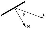
Diffuse Reflection :
Dull, matte surfaces, such as chalk, exhibit diffuse reflection, which is also known as Lambertian reflection. Such surfaces appear equally bright from all viewing angles because they reflect light with equal intensity in all directions. The resulting intensity due to diffuse Reflection is given by \(I = K_dI_pcos\theta\) where \(I_p\) is the intensity of the point light source. \(K_d\) is the coefficient of diffuse reflection, which is a constant for a specific material and ranges in the interval \([0, 1]\) and \(\theta\), angle of incidence is the angle measured between between the direction from p to the point light source and the normal to the surface
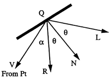
Specular Reflection :
Specular reflection is observed on any shiny surface. For example, when an apple is illuminated with a white light, a bright spot is found in the illuminated region of its surface, which adds a ‘shine’ to it. If one moves his ahead, the bright spot also moves a bit. This means the distribution of illumination is subject to the viewer’s position. This is called specular reflection. The resulting intensity due to diffuse Reflection is given by \(I = K_sI_pcos^n\alpha\) where \(K_s\) is the material’s specular-reflection coefficient, ranging in \([0, 1]\), and \(n\) is its specular-reflection exponent. A higher value of \(n\) creates a smaller and brighter spot. \(\alpha\) is the angle between direction from point to camera and the reflected ray.
To account the fact that the energy from a point light source falls off as the inverse square of d, the distance traveled by the light wave, we have multiplied diffuse and specular components with an attentuation factor, \(f_{att}\) which is calculated as \( f_{att} = min(\frac{1}{c_1+c_2d+c_3d^2},1)\).
So, the final expression of intensity of light at a point p is given by :
\(I = K_aI_a + f_{att}\ ( K_dI_pcos\theta\ + K_sI_pcos^n\alpha\))
Method followed to get final RGB value of a pixel :
RGB model is not intuitive enough for us to understand intensity of light. So, we use HSV color model for intensity calculations.
- Find HSV values from the material RGB values.Now we made H,S fixed and change V according to the Intensity of the point calculated as above.
- If the point is shadow ,we made diffuse,specular components zero. We initially set V to sum of all the above mentioned intensity components.
- In order to make V in the range \([0,1]\) we normalized the V values.
- Normalization technique used : we found the max V value per colour and divided all the V values of this particular colour with this max V value.
- Now we recalculated the RGB values from the current HSV values and used these RGB values for the pixel.
Results
Summary
In summary,
- We used ray casting to create realistic images.
- We can make it more realistic using further techniques like applying textures and using recursive ray tracing.
- All ray tracing techniques require very high compute power. But, these algorithms are highly parralelizable. Using GPUs, we can drastically reduce running time.
References and image sources
- Computer Graphics : Selected Lecture Notes by Partha Bhowmick
- An overview about ray tracing