My Research Page
|
|
Matching and analysis of patterns or shapes in the digital plane are of utmost importance in various problems of computer vision and pattern recognition. A digital point set is such a pattern that corresponds to an object in the digital plane. Although there exist several data structures that can be employed for Approximate Point Set Pattern Matching (APSPM) in the real domain, they require substantial modification to support algorithms in the digital domain. To bridge this gap, a novel data structure called angular tree is devised by us, targeting an efficient and error-controllable circular range query in the digital plane. The farthest pair of points may be used as the starting correspondence between the pattern set and the background set. Several classical discrete structures and methodologies of computational geometry as well as some topological features of circles/discs in digital geometry have been used in tandem, for successful realization of the proposed APSPM algorithm in the digital plane. The APSPM algorithm based on the angular tree has been implemented and tested on various point sets, and the reported results demonstrate the efficiency and versatility of the new data structure for supporting APSPM algorithms. |
||
Corners detected in a real-world image by our algorithm.
These corners act as the representative set in the matching scheme. |
 Directions of the edges incident at each corner are also estimated by our algorithm (a specialty of our algorithm) to aid the subsequent matching. |
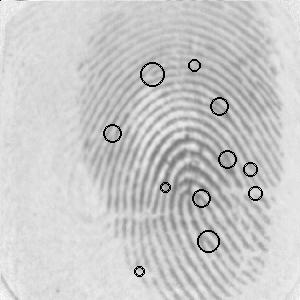 Minutiae detected along with their scores (a larger circle indicates a higher score, i.e., a better minutia) in a fingerprint image by our algorithm. These minutiae constitute a set of digital points used as the input in our Automatic Fingerprint Identification System (AFIS). |
|
||
|
Approximate Straightness |
|||||||||||||||||||||||
 |
Given
a sequence of points, an interesting problem is to decide whether the points
are collinear. The problem is really challenging when the problem is to find
an optimal or a sub-optimal set of line segments, each of which fits or
represents a (piecewise linear) subsequence of the input point-sequence.
Several methods for (approx.) line fitting are there, mostly based on
certain distance criteria, usage of masks, eigenvalue analysis, the Hough
transform, and so forth. These methods, however, do not solve the problem in
the digital plane and resorts to Euclidean metric applicable in the real
plane. |
||||||||||||||||||||||
|
The problem of fitting line segments becomes more engrossing in the digital plane where Euclidean geometry fails to work and the concept of digital geometry comes into play. The notion of digital straightness is, therefore, introduced by many celebrated digital-geometers like Bruckstein, Freeman, Klette, Povazan, Rosenfeld, and many others. We studied and analyzed the digital-geometric properties of digital straight segments (DSS), and on exhaustive testing, found that DSSs requied to (piecewise and linearly) fit a digital curve (a connected sequence of digital points) are quite large in number and quite small in their individual lengths. Hence, we have relaxed certain properties of DSS to bring forth a new concept of approximate straightness on the digital plane. This leads to a practical realization of approximate DSS (ADSS). The number of ADSS required to cover a digital curve is found to be significantly fewer than that of the exact DSS cover. The extracted set of ADSS can further be combined to determine a compact polygonal approximation of the digital curve based on certain approximation criteria and a specified error tolerance. The proposed algorithm involves only primitive integer operations (a feature of the digital paradigm!) and, thus, runs very fast compared to the other algorithms. The overall time complexity becomes linear in the number of points present in the representative set. See more |

|
||||||||||||||||||||||
|
||||||||||||||||||||||||||||||||
|
||||||||||||||||||||||||||||||||


|
Inner and outer covers of a digital object An isothetic representation |
||
 |
 |
The
problem of finding an optimal outer (or inner) polygonal envelope, imposed
by isothetic grid lines, for an object, is a grave and critical one, and its solution can be
useful to many interesting applications, such as:
Challenge of the problem:
At each grid point, a
decision has to be made for the next path to be followed. It may so happen
that a current decision based on the local arrangement, may eventually
lead to a situation where no further advancements can be made. As a
result, it may become mandatory to revoke the earlier decisions in order
to backtrack and branch out iteratively until the final solution is found,
which would incur excessive computational cost. |
|
||
|
Isothetic Convex Envelope An approximate convex hull in the digital plane |
|||||||||||||||||||||||||||||||||||
 |
 |
 |
 |
||||||||||||||||||||||||||||||||
|
A
digital object A (set of blobs) and its isothetic envelope IE(A) |
Digital straight edges of IE(A) | The convex envelope CE(A) of the straight edges of IE(A) | ICE(A): The isothetic convex envelope of A | ||||||||||||||||||||||||||||||||
|
I CE is defined as the isothetic convex polygon that contains a given digital object. An ICE is not necessarily a (isothetic) convex hull, since the former is dependent on the underlying isothetic grid opposed to the latter. In order to derive the ICE of an object in accordance with the grid specification, the real convex hull of its (non-convex) isothetic envelope (IE) is used, and the process is expedited by considering only (the end points of) the straight edges of the IE in an incremental version of a classical algorithm of computational geometry. Slackening the tightness of an ICE corresponding to a digital object is achievable by increasing the grid size, and for a slackened ICE with lesser output complexity (i.e., with lesser number of vertices), the runtime of the algorithm falls significantly. The proposed algorithm is marked by its dependence on object boundary instead of object size, and usage of primitive integer operations in the digital domain, which, in entirety, ensures its speedy execution and acceptability in a real-world application. |
 |
||||||||||||||||||||||||||||||||||
|
|||||||||||||||||||||||||||||||||||


|
Digital Circularity |
|||||||
|
|
||||||


|
Digital circles, abiding with their weird and challenging nature in the discrete domain, have drawn immense research interest since the early adoption of the scan-conversion technique for their efficient approximation from the continuous domain to the digital domain. Subsequent improvements of these algorithms meant for generation of circular arcs were achieved by different researchers in the later periods. Further, apart from the circle-generation algorithms, since the properties, parameterization, characterization, and recognition of digital circles and circular arcs shape up a very engrossing area of research, several other interesting works on digital circles and related problems have also appeared from time to time. However, the essence of all these algorithms is that, although a circle drawing algorithm primarily originates from the naive concept of intelligent digital applications of first-order and second-order derivatives (differences) as in Bresenham�s, a digital circle is endowed with some other interesting properties contributed by the classical theories in the discrete domain. It has been gradually made apparent from these works that digital circles, similar to digital straight lines, possess some striking characteristics, which, if interpreted rightly and exploited properly, may produce interesting results and scope for subsequent potential applications in the discrete domain. Our number-theoretic interpretation reveals the relation between perfect squares (square numbers) in discrete (integer) intervals and few interesting and useful properties of a digital circle. Based on these number-theoretic properties, the problem of constructing a digital circle or a circular arc maps to the new domain of number theory. However, the construction of a digital circle using these properties should not be looked upon as a competition with Bresenham�s algorithm or any other similar algorithm; rather, these number-theoretic properties enrich the understanding of digital circles from a perspective that is different from the customary aspects of digital calculus. We have also shown how these intervals can be obtained for the given radius of a circle, and what effects these intervals have on the construction of a digital circle. |
|
|||
|
P. Bhowmick and B. B. Bhattacharya, Number-Theoretic Interpretation and Construction of a Digital Circle. Discrete Applied Mathematics, Volume 156, Issue 12, June 2008, Pages 2381-2399. |
||||
 A demonstration of the algorithm DCR for r = 106 until a run of unit length is found. For each row, the binary search (steps 4-10) is illustrated by circular dots, where each dot corresponds to the middle element (m) of the respective sub-array (square[s..t]). Notice that, m (in step 6) denotes the abscissa (vertical) line x = m-1 in the figure. As the binary search, associated with a particular row, proceeds and converges to produce the final run of the corresponding row, the respective dots have been gradually darkened to depict the impact of the run length finding procedure. The end of the run at each row is emphasized by highlighted abscissa lines passing through the end point of that run for visual clarity. For instance, for the topmost row, m starts with 53, followed by 26, 13, and so on, until s = t = 11. Hence, m finally becomes 11, thereby yielding the run length equal to 11. So, for j=106, i=0 to i=10. Similarly, for the next row, since the start values of s and t are 11 and 23 respectively, the subsequent values of m are 17, 20, 19, and (finally) 18, which makes the corresponding run length to 18-11 = 7. So, for j=105, i=11 to i=17, as shown in the figure. Thus, the run length of a particular row (y = j) is given by the cumulative run length up to that row minus the preceding cumulative run length, which is realized by the function include_run (i, s-i, j) in step 6 of the algorithm. |
||||
|
Digital Curves in Fingerprints Fingerprints, produced by the ridge and valley patterns on the tip of a finger, have been used for biometric authentication for quite a long time owing to their uniqueness and immutability. Apart from criminal identification, fingerprint verification has become more popular today in many civilian applications, e.g., access control, financial security, employee identification, verification of firearm purchasers, driver license applicants, etc. [Maltoni et al.: Handbook of Fingerprint Recognition, 2003]. A wide range of fingerprint matching algorithms exists, mostly based on the long-established forensic procedures of minutia matching. Minutiae are local discontinuities of ridgelines in a fingerprint pattern. ANSI has proposed a minutiae-classification based on four classes: terminations, bifurcations, crossovers, and undetermined. In practice, most of the AFIS follow the two-class minutiae classification: termination and bifurcation, used by the FBI. Since in a fingerprint image, trifurcation minutiae and undetermined minutiae, if present, are very few in number, we have adopted the FBI model, and have not considered them as valid features but as points of discontinuity on the concerned ridgelines. |
 |
||||||||||||||||


Selecting control points (red pixels) with increasing density (i.e., decreasing separation) near a minutia ensures little or no deviation of the corrected ridgeline from its original location near the corresponding minutia. |
|||||||||||||||||
|
An optimal value of tau should be chosen, therefore, depending upon the characteristics of the input fingerprint image and the subsequent purpose of using the output image. A value of tau in the range [1, 2] produces desired results, as observed in our experiments with the four benchmark image databases we have considered. |
 |
||||||||||||||||
|
|||||||||||||||||
T. Acharya, B. B. Bhattacharya, P. Bhowmick, A. Bishnu, J. Dey, M. K. Kundu, and C. A. Murthy, Architecture for Processing Fingerprint Images, US Patent No. 6,795,592, issued on 21/09/04. T. Acharya, B. B. Bhattacharya, P. Bhowmick, A. Bishnu, J. Dey, M. K. Kundu, and C. A. Murthy, Method and Apparatus for Providing a Binary Fingerprint Image, US Patent No. 7,136,515, issued on 14/11/2006. T. Acharya, B. B. Bhattacharya, P. Bhowmick, A. Bishnu, J. Dey, M. K. Kundu, and C. A. Murthy, Method and Apparatus to Reduce False Minutiae from a Binary Fingerprint Image, US Patent pending (Publication Application # 20030063782, April 2003). T. Acharya, B. B. Bhattacharya, P. Bhowmick, A. Bishnu, A. Biswas, M. K. Kundu, C. A. Murthy, S. Das, and S. C. Nandy, Minutia Matching using Scoring Techniques, US Patent pending (Publication Application # 20050129293, Dec 2003). P. Bhowmick and B. B. Bhattacharya, Approximate Fingerprint Matching Using Kd-tree, ICPR 2004, vol. I, pp. 544-547. A. Bishnu, P. Bhowmick, S. Dey, B. B. Bhattacharya, M. K. Kundu, C. A. Murthy, and T. Acharya, Combinatorial Classification of Pixels for Ridge Extraction in a Gray-scale Fingerprint Image, ICVGIP 2002, pp. 451-456. P. Bhowmick, A. Bishnu, B. B. Bhattacharya, M. K. Kundu, C. A. Murthy, and T. Acharya, Determination of Minutiae Scores for Fingerprint Image Applications, ICVGIP 2002, pp. 463-468. |
|||||||||||||||||


|
Geometric Properties of Corners An application in GIS |
|||||||||||||||||||||||||
 |
|||||||||||||||||||||||||
|
Recognition and classification of various ground objects in a remotely sensed map are often required for designing powerful geographical information systems (GIS). Over the last few decades, several methodologies have been developed for the detection and subsequent analysis of buildings, industrial regions, and geographical landmarks (e.g., coastlines, roads, etc.). Our work deals with the problem of identifying the super built-up areas that follow a rectilinear pattern, using the corners and the associated straight edges present in the concerned image. In order to detect the corners and related information, our algorithm uses an annular window (whose radius is iteratively augmented depending on certain conditions) at each possible corner point to estimate the directions of the incident edges at that point. An annular filtering scheme to process the noisy data appropriately before estimating the orientations of incident edges, and a variable threshold of gray value transition parameter depending on the radius of the annular window, are employed to aid the process. The estimated directions of the edges from the corners are used, in turn, to find the (corner-to-corner as well as pre-terminating) straight edges. A fast analysis of these straight edges produces the rectilinear set of edges, which represents the perimeter of the corresponding super built-up structure in an elegant way. |
|||||||||||||||||||||||||
|
|||||||||||||||||||||||||
|
P. Bhowmick and B. B. Bhattacharya, GRASP: Geometric Recognition of Corner-to-Corner Straight Pieces in an Aerial Map. International Symposium on Data, Information & Knowledge Spectrum (ISDIKS 2007), 2007 (accepted). |
|||||||||||||||||||||||||


Thank you
for visiting my research page...
If you have any
suggestion, please send to
pbhowmick@iitkgp.ac.in
Partha Bhowmick, 2008.